Ninotnc config
NinoTNC DIP switch settings
These settings apply to the most recent version of NinoTNC (A4). To see older settings, refer to the full operator's manual.
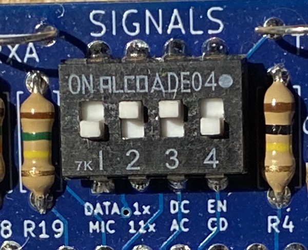
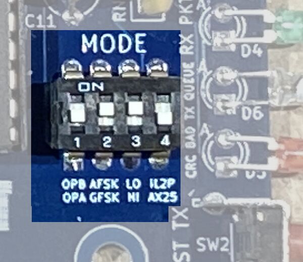
There are two sets of DIP switches on the NinoTNC. Those on the top edge control how to communicate with the model of radio you have attached it to, and those along the bottom edge control the baud rate and mode.
Top DIP switches ("SIGNALS")

| # | Label | Effect |
|---|---|---|
| 1 | DATA / MIC | ON - Use if your radio uses a direct data connection to the TNC.
OFF - Use if your radio has an audio cable connection to the TNC (i.e. connected to its microphone jack). |
| 2 | 1x / 11x | ON (typical) - Incoming audio is processed at the received volume from the radio (1x).
OFF - Boosts incoming audio from the radio 11x, to compensate for some radios with very low audio output (e.g. Kenwood TM-221A which provides audio out via its mic connector). |
| 3 | DC / AC | ON (typical) - No decoupling capacitor is inserted between the NinoTNC audio output and the radio.
OFF - A decoupling capacitor is inserted between the NinoTNC audio output and the radio. Some radios will distort audio without this, such as Tait radios. |
| 4 | EN / CD | ON - Allows an external device to block the TNC from transmitting by grounding pin 2 of the DE-9 connector.
OFF (typical) - Ignores pin 2 of the DE-9 connector. |
Bottom DIP switches ("MODE")

| Setting | Effect |
|---|---|
| 0-0-0-0 | 9600 baud AX.25 |
| 0-0-0-1 | 9600 baud IL2P |
| 0-0-1-0 | 4800 baud AX.25 |
| 0-0-1-1 | 4800 baud IL2P |
| 0-1-0-0 | 2400 baud AX.25 |
| 0-1-0-1 | 2400 baud IL2P |
| 0-1-1-0 | 1200 baud AX.25 |
| 0-1-1-1 | 1200 baud IL2P |
| 1-1-0-0 | 300 baud AX.25 |
| 1-1-0-1 | 300 baud IL2P |
| 1-1-1-0 | 150 baud AX.25 |
| 1-1-1-1 | 150 baud IL2P |
NinoTNC audio settings
Receive audio level
Adjust the audio of the radio attached to the NinoTNC until the left-most red LED just stops flickering. Adjust it a bit too high at first (start flickering), then dial it back until the flickering stops. The audio of the radio is the receive audio level of the NinoTNC. If your radio has a direct data connection (e.g. DE-9 connector) it may not honor the volume setting, and instead have a fixed value. In that case, use the DATA dip switch (see above) and the volume will be fixed.
If you cannot get the left-most red LED to flicker at all, you may need to enable the 11x DIP switch (see above).
Transmit audio level
The "TX DEV" potentiometer (small dial you can adjust with a screwdriver) on the left of the NinoTNC controls your transmit audio volume. Turn this up only as high as needed for your neighbor to cleanly receive your signal. If unsure, set it somewhere in the middle and adjust it up and down during a linktest until your neighbor receives nearly all your test messages.
Transmit delay
Since radios don't transmit instaneously, a short delay is needed between when the NinoTNC has outgoing data to send, and the radio is prepared to receive it. The "TX DELAY" potentiometer on the right of the NinoTNC controls the transmit delay. Listen to NinoTNC's signal on another radio (e.g. an HT), hit the test button, and adjust the transmit delay until you just hear a short tone before the packet audio (which sounds like static). The delay is accomplished by playing a tone for a fixed duration before each transmit. If you're hearing a very long tone before the packet, the transmit delay is set too high.