Ninotnc config: Difference between revisions
No edit summary |
No edit summary |
||
| Line 5: | Line 5: | ||
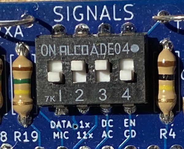
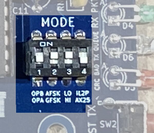
There are two sets of DIP switches on the NinoTNC. Those on the top edge control how to communicate with the model of radio you have attached it to, and those along the bottom edge control the baud rate and mode. | There are two sets of DIP switches on the NinoTNC. Those on the top edge control how to communicate with the model of radio you have attached it to, and those along the bottom edge control the baud rate and mode. | ||
Top DIP switches: | === Top DIP switches (labeled "SIGNALS"): === | ||
[[File:Signals-switch-0110-img-3128-600x488.jpg|alt=Photo of SIGNALS DIP switches on the top of a NinoTNC PCB|left|thumb|600x600px|Photo of top DIP switches]] | |||
{| class="wikitable" | |||
|+ | |||
!# | |||
!Label | |||
!Purpose | |||
|- | |||
|1 | |||
|DATA / MIC | |||
|ON - Use if your radio uses a direct data connection to the TNC. | |||
OFF - Use if your radio has an audio cable connection to the TNC (i.e. connected to its microphone jack). | |||
|- | |||
|2 | |||
|1x / 11x | |||
|ON (typical) - Incoming audio is processed at the received volume from the radio (1x). | |||
OFF - Boosts incoming audio from the radio 11x, to compensate for some radios with very low audio output (e.g. Kenwood TM-221A which provides audio out via its mic connector). | |||
|- | |||
|3 | |||
|DC / AC | |||
|ON (typical) - No decoupling capacitor is inserted between the NinoTNC audio output and the radio. | |||
OFF - A decoupling capacitor is inserted between the NinoTNC audio output and the radio. Some radios will distort audio without this, such as Tait radios. | |||
|- | |||
|4 | |||
|EN / CD | |||
|ON - Allows an external device to block the TNC from transmitting by grounding pin 2 of the DE-9 connector. | |||
OFF (typical) - Ignores pin 2 of the DE-9 connector. | |||
|} | |||
=== Bottom DIP switches: === | |||
[[File:A4-mode-switch-sw1-top-down-img-1998-x955x826.jpg|alt=Photo showing bottom DIP switches on a NinoTNC PCB|left|thumb|600x600px|Photo of bottom DIP switches]] | |||
{| class="wikitable" | {| class="wikitable" | ||
|+ | |+ | ||
Revision as of 14:03, 26 April 2023
NinoTNC DIP switch settings
These settings apply to the most recent version of NinoTNC (A4). To see older settings, refer to the full operator's manual.
There are two sets of DIP switches on the NinoTNC. Those on the top edge control how to communicate with the model of radio you have attached it to, and those along the bottom edge control the baud rate and mode.
Top DIP switches (labeled "SIGNALS"):

| # | Label | Purpose |
|---|---|---|
| 1 | DATA / MIC | ON - Use if your radio uses a direct data connection to the TNC.
OFF - Use if your radio has an audio cable connection to the TNC (i.e. connected to its microphone jack). |
| 2 | 1x / 11x | ON (typical) - Incoming audio is processed at the received volume from the radio (1x).
OFF - Boosts incoming audio from the radio 11x, to compensate for some radios with very low audio output (e.g. Kenwood TM-221A which provides audio out via its mic connector). |
| 3 | DC / AC | ON (typical) - No decoupling capacitor is inserted between the NinoTNC audio output and the radio.
OFF - A decoupling capacitor is inserted between the NinoTNC audio output and the radio. Some radios will distort audio without this, such as Tait radios. |
| 4 | EN / CD | ON - Allows an external device to block the TNC from transmitting by grounding pin 2 of the DE-9 connector.
OFF (typical) - Ignores pin 2 of the DE-9 connector. |
Bottom DIP switches:

| Setting | Effect |
|---|---|
| 0-0-0-0 | 9600 baud AX.25 |
| 0-0-0-1 | 9600 baud IL2P |
| 0-0-1-0 | 4800 baud AX.25 |
| 0-0-1-1 | 4800 baud IL2P |
| 0-1-0-0 | 2400 baud AX.25 |
| 0-1-0-1 | 2400 baud IL2P |
| 0-1-1-0 | 1200 baud AX.25 |
| 0-1-1-1 | 1200 baud IL2P |
| 1-1-0-0 | 300 baud AX.25 |
| 1-1-0-1 | 300 baud IL2P |
| 1-1-1-0 | 150 baud AX.25 |
| 1-1-1-1 | 150 baud IL2P |